 EN
EN

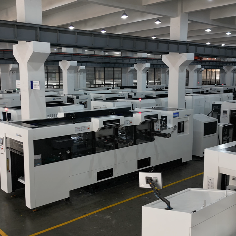
In modern packaging and print finishing operations, the performance of a cut and die machine is measured by two defining parameters: speed and accuracy. These two factors directly influence production throughput, material waste, and final product quality. Whether you are running short runs of folding cartons or high-volume corrugated packaging, understanding what actually drives the speed and precision of a cut and die machine is essential for making intelligent procurement and operational decisions.
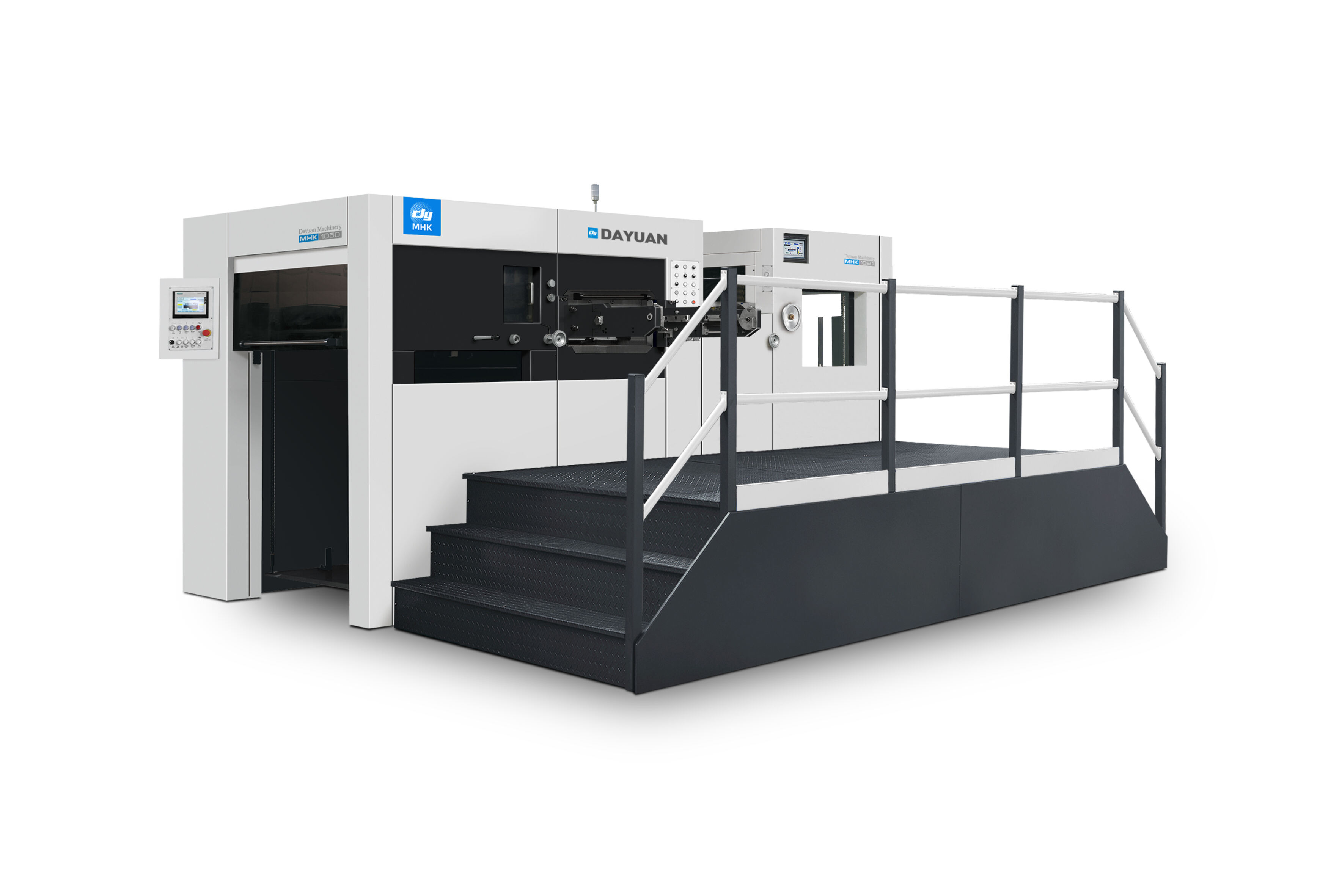
A cut and die machine that performs inconsistently — even by fractions of a millimeter — can cause significant downstream problems, including misaligned folds, poor glue adhesion, and rejected print jobs. At the same time, a machine that sacrifices speed for precision creates production bottlenecks that erode profitability. This article breaks down the key mechanical, electronic, and operational factors that together determine how fast and how accurately a cut and die machine performs in a real production environment.
Mechanical Architecture and Its Role in Performance
Frame Rigidity and Structural Stability
The physical construction of a cut and die machine has a direct and lasting impact on both its cutting accuracy and its sustainable operating speed. Machines built on heavy-duty cast iron or welded steel frames exhibit far less vibration during high-speed cycles than those constructed from lighter materials. Vibration is the enemy of precision — even minor oscillations can cause the cutting die to contact the substrate at a slightly different angle or position, leading to dimensional inconsistencies across a production run.
Frame rigidity also affects the machine's ability to maintain press parallelism over time. When the top and bottom platens are not perfectly parallel, the cutting pressure is distributed unevenly, resulting in partial cuts, crushed creases, or die wear that accelerates unexpectedly. A well-engineered cut and die machine uses precision-ground guide columns and adjustable platen leveling systems to compensate for any minor deviations introduced by manufacturing tolerances or long-term operational wear.
Structural integrity also plays into the machine's maximum operating speed. A rigid frame can absorb and distribute the cyclical impact loads of repeated die-cutting strokes without fatigue, allowing the machine to sustain rated speeds over a full production shift. Lighter or less rigid machines tend to slow down under sustained load to avoid quality degradation, effectively reducing their real-world throughput below the stated specification.
Drive System Design and Mechanical Precision
The drive system — whether eccentric shaft, toggle-link, or servo-driven — determines how consistently the cutting stroke is executed. In a traditional eccentric shaft design, the motion curve is mechanically fixed, meaning the platen descends and ascends at a rate determined purely by cam geometry. While reliable, this system provides limited flexibility for adjusting the stroke profile to suit different substrate types or cutting die complexities. Toggle-link mechanisms, used in many high-performance versions of the cut and die machine, offer a more favorable force curve, delivering maximum press force precisely at the bottom of the stroke where it is needed most.
Servo-driven systems represent the current frontier in drive technology, allowing programmable stroke profiles that can be optimized for each job. This adaptability means the machine can accelerate through the non-cutting portions of the cycle and slow precisely as the die contacts the material, maximizing both sheet throughput and cutting quality. The accuracy of the drive system's positioning — measured in microns — is a core determinant of registration consistency across a production run.
Feeder and Delivery System Precision
Sheet Registration and Alignment Mechanisms
Even the most mechanically precise cut and die machine cannot deliver accurate results if the sheet enters the cutting station misaligned. The feeder system is therefore a critical contributor to overall accuracy. Modern automatic feeders use a combination of front lay gauges, side lay guides, and pull gauges to ensure that every sheet arrives at the cutting platen in exactly the same position, within tolerances typically measured in tenths of a millimeter.
Suction head design and air management systems significantly influence how cleanly sheets are separated and advanced, particularly when handling coated papers, laminated boards, or other substrates prone to static buildup or sheet-to-sheet adhesion. Machines equipped with variable-suction feeders can handle a broader substrate range without compromising registration accuracy, making them more versatile in multi-product production environments. The overall quality of the feeder system is one of the most frequently underestimated factors when evaluating the accuracy capability of a cut and die machine.
Sheet Delivery and Pile Management
At the output end, the delivery system must handle cut sheets cleanly and at speed without introducing distortion or pile misalignment. Jogger systems, nonstop pile changers, and controlled deceleration mechanisms all contribute to orderly sheet delivery. A poorly designed delivery can cause jams at high speeds, which interrupt production and require manual intervention. More critically, if the delivery mechanism allows cut sheets to shift before the pile is squared, the apparent accuracy of the die-cutting may appear worse than it actually is when the pile is evaluated.
Consistent pile management also reduces post-process handling time, contributing indirectly to overall line efficiency. In a fully optimized cut and die machine workflow, the feeder, cutting station, and delivery system function as an integrated unit, each tuned to match the others in terms of speed and rhythm. Any imbalance in this system creates either speed restrictions or accuracy compromises.
Die Tooling Quality and Maintenance
Die Construction and Rule Specifications
No matter how precise the machine, the quality of the cutting die itself is a fundamental determinant of output accuracy. Steel rule dies must be made with high-quality rule stock, laser-cut boards of appropriate thickness, and precise bending to achieve the intended cut geometry. Rule height consistency across the entire die face is critical — even a 0.1mm difference in rule height across a large die can cause inconsistent cut depth and require excessive cutting pressure adjustments that stress the machine structure.
The relationship between rule type and substrate is also important. Using the wrong rule profile — for example, a single-bevel rule on a substrate that requires a center-bevel — can result in ragged cut edges or excessive sheet deformation at crease lines. Operators using a cut and die machine for diverse applications must maintain a range of rule specifications and ensure that dies are correctly specified for each substrate and job type. This tooling discipline is as important as any machine setting in achieving consistent cutting accuracy.
Die Wear and Replacement Cycles
Cutting rules are consumable components. As they wear, cut quality degrades progressively — edges become less clean, more force is required, and crease lines lose definition. A production team that does not have a systematic approach to monitoring and replacing worn dies will experience gradual accuracy degradation that can be difficult to attribute to the tooling rather than the machine. Implementing run-count tracking for each die and establishing clear replacement thresholds is a best practice that directly supports consistent output quality from a cut and die machine.
Ejection rubber also plays a role in accuracy. Rubber strips or foam pads surrounding cutting rules must have the correct hardness and height to cleanly eject cut pieces without dragging or distorting them. Worn or incorrectly specified ejection rubber is a common cause of cut piece displacement within the die, leading to double-cut defects or irregular crease formation.
Control Systems, Automation, and Digital Integration
CNC and PLC Control Architecture
Modern versions of the cut and die machine are equipped with sophisticated PLC or CNC control systems that manage every aspect of the cutting cycle. These systems allow operators to store job parameters — including cutting pressure, feeder speed, register position, and delivery settings — as named programs that can be recalled instantly when a job is repeated. This programmability dramatically reduces setup time between jobs, which is a significant contributor to overall production speed in facilities running mixed job queues.
Advanced control systems also incorporate real-time monitoring of key operating parameters, including press parallelism, stroke count, and motor load. When deviations are detected, the control system can alert the operator or make automatic micro-corrections to maintain accuracy. This closed-loop feedback capability is what separates a high-performance cut and die machine from a basic mechanical press, particularly in demanding applications where tolerance requirements are tight.
Servo Motor Integration and Speed Stability
The integration of servo motor technology into feeder, delivery, and auxiliary systems of a cut and die machine has a measurable impact on both speed and accuracy. Servo-controlled feeders can accelerate and decelerate sheets more precisely than mechanical cam-driven systems, enabling higher throughput speeds without sacrificing registration accuracy. Servo delivery systems similarly provide more controlled sheet handling at output, reducing the tendency for high-speed delivery to cause pile disorder.
Speed stability during the cutting stroke is another factor that benefits from servo technology. In machines where the main drive motor is servo-controlled, the press speed remains consistent regardless of the cutting resistance offered by different substrates or die configurations. This consistency means that the time-position relationship of the sheet in the cutting station is predictable, supporting accurate registration and uniform cut depth across every sheet in the run.
Operational Variables That Affect Speed and Accuracy
Substrate Characteristics and Material Handling
The substrate being processed has a substantial influence on both the achievable speed and the cutting accuracy of a cut and die machine. Stiff, flat substrates with consistent caliper feed more reliably and can typically be run at higher speeds than limp, uneven, or humidity-affected materials. Moisture content variations in board stock cause dimensional instability, which can introduce registration errors that persist even when the machine itself is performing correctly.
Coated and laminated substrates present specific challenges related to static electricity and sheet separation. Without proper ionization or anti-static treatment, sheets may double-feed or fail to separate cleanly from the pile, causing registration errors or machine stops. Operators working with challenging substrates on a cut and die machine need to account for these material-specific behaviors in their setup procedures and may need to reduce operating speed to maintain consistent quality.
Operator Skill and Setup Discipline
Even the most capable machine is limited by the quality of its setup and operation. An experienced operator understands how to optimize cutting pressure to achieve clean cuts without over-compressing the substrate, how to fine-tune register settings for each job and material combination, and how to identify early signs of die wear or mechanical deviation before they translate into reject rates. Operator skill is particularly influential at the boundaries of machine capability, where marginal substrate conditions or complex die geometries require judgment that no automated system can fully replace.
Setup time itself is a component of speed in the broader production context. A machine that is technically fast but requires long setup times between jobs may deliver lower net throughput than a slightly slower machine with excellent job management systems. This is why the combination of intuitive control software, well-documented job programs, and skilled operators is often more decisive for real-world productivity than raw sheet-per-hour ratings alone. The best outcomes from a cut and die machine are always the product of aligned mechanical capability and operational excellence.
FAQ
What is the main mechanical factor that limits the speed of a cut and die machine?
Frame rigidity and drive system design are the primary mechanical limiters. A machine with a rigid frame and a well-engineered toggle or servo drive can sustain higher cycle rates without introducing vibration-related accuracy loss. Machines that vibrate excessively at high speeds must be throttled back to maintain acceptable cut quality, reducing their effective throughput below the nameplate rating.
How does die quality affect the accuracy of a cut and die machine?
Die quality is directly linked to output accuracy. Inconsistent rule heights, incorrect rule profiles, or worn cutting rules all degrade cut precision and crease definition. A high-quality cut and die machine cannot compensate for poor die construction. Maintaining strict die specification standards and implementing systematic wear monitoring are essential for sustaining consistent accuracy over production runs.
Can substrate variation cause accuracy problems even on a well-maintained cut and die machine?
Yes. Substrates with caliper inconsistency, moisture-induced dimensional variation, or static-induced feeding problems can introduce registration errors even when the machine is in perfect mechanical condition. Proper material conditioning, appropriate feeder settings, and sometimes reduced operating speed are necessary to manage substrate-related accuracy challenges on any cut and die machine.
How does automation and digital control improve the performance of a cut and die machine?
Digital control systems improve performance by enabling rapid job recall, reducing setup time, and providing real-time monitoring that catches deviations before they cause quality failures. Servo integration adds precision to feeder and delivery motion, supporting higher consistent speeds. Together, these technologies allow a modern cut and die machine to deliver more predictable, repeatable performance across diverse job types and substrate specifications.
Table of Contents
- Mechanical Architecture and Its Role in Performance
- Feeder and Delivery System Precision
- Die Tooling Quality and Maintenance
- Control Systems, Automation, and Digital Integration
- Operational Variables That Affect Speed and Accuracy
-
FAQ
- What is the main mechanical factor that limits the speed of a cut and die machine?
- How does die quality affect the accuracy of a cut and die machine?
- Can substrate variation cause accuracy problems even on a well-maintained cut and die machine?
- How does automation and digital control improve the performance of a cut and die machine?